Display · Hardware
LCD contrast at different voltages
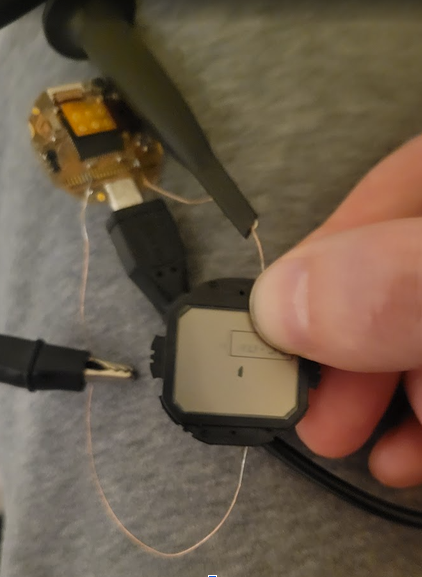
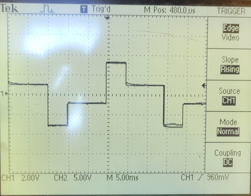
When making the Jolt, one of my largest goals was to offer compatibility with the Sensorwatch codebase, which was made for the SAML22 chipset. I know that the F91W only needs 3V for its LCD, and from Googling around, it seems that the G-Shock uses a display that needs 4 to 4.5V. The SAML22 has a max output of 3.4V. While that’s a distance from 4V, it’s still worth testing how the contrast may look on the G-Shock display. As a first attempt, I soldered a SEG and COM pins on the original Sensorwatch to a COM and SEG pin of the original G-Shock PCB. You can see the result in Fig. 1 and the waveform of the SEG in Fig. 2. That pixel was enough for me to be comfortable to keep going.
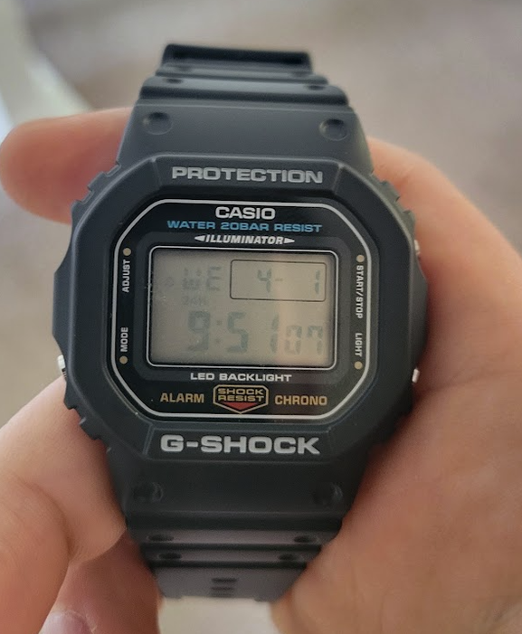
After developing an alpha board, I was finally able to get the LCD working to see how well the contrast would actually be. And it was more disappointing than what I expected from Fig 1. It turns out that while the F91W uses a ⅓ duty on the LCD waveform, the G-SHock uses a ¼ duty. That may lead to a lower RMS voltage on any of the pins, leading to a dimmer LCD segment. Fig 3. Shows what it looks like at 3.4V. Not great.
3.4 volts - The Failed First Attempt
Reading further into the datasheet, I saw that there is the capability to use an external voltage to power the LCD, but the max voltage is 3.6V. It’s not huge, but any little bit should help. I rigged up a test to see how the watch looks at different voltages in the video below (Fig 4). I found that 3.6V was workable, 3.8 V was great, and 4V was near ideal. I found a low-current convertor that can take the voltage from the battery and boost it to any one of those. I selected one that can have its output voltage changed with a resistor and found the voltage divider options so that it defaults to 3.6V, but if the right resistor is soldered onto another section of the board, 3.8, 4, 4.3, and even 4.5V are possible.
Once I got the watch with 3.6V, I retested the contrast and it’s better. But I wanted to know if it could be pushed further.
Once I had the watch running at 3.6 V, I retested the contrast and it was better. I still wanted to know whether it could be pushed further.
3.6 volts - What Will Come Stock
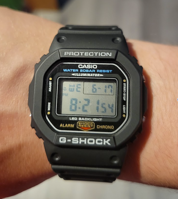
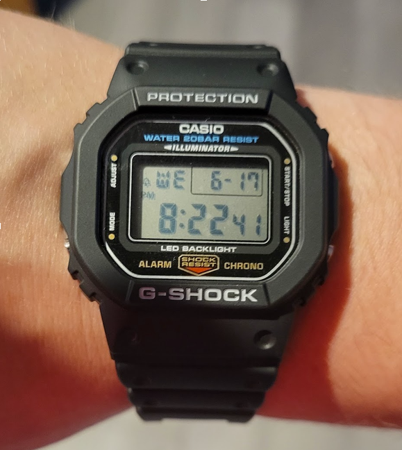
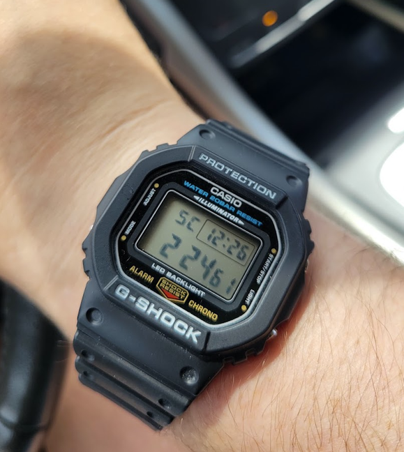
To give an example of the difference in viewing angle, here's a picture of the watch at 3.6V from a member in the community. The poor contrast goes away at most angles aside from head-on.
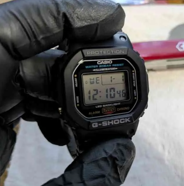
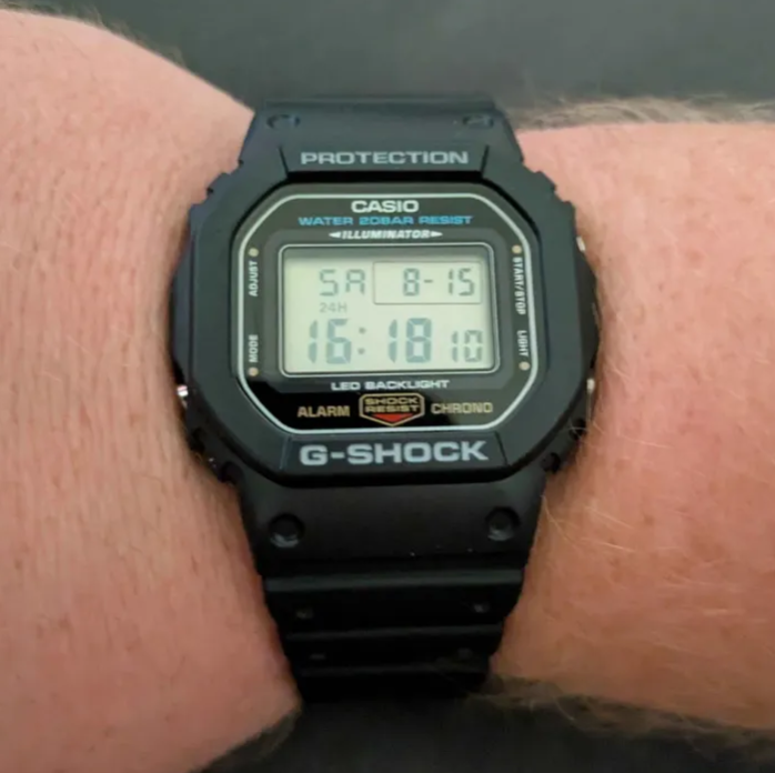
I reached out to Microchip, the producer of the SAML22 and asked about driving the LCD to 4V. As expected, they said that it’s outside of the datasheet spec and they can’t provide feedback on running at a higher voltage without them characterizing it themselves (with a business qualification and fee). I have a background in transistor quality engineering in a previous role, so I asked if the root cause is related to gate-oxide breakdowns in the LCD circuitry. Microchip’s support stated it would be due to breaking down of protection diodes leading to several power domains shorting. Like gate-oxide breakdowns, this is a failure mechanism that causes the part to slowly break down over time, but also may never be an issue. They did suggest external voltage translation or level-shifting, but either of those would eat up board space I didn’t have and add heavily to the power budget. I also considered moving to a different chip altogether, such as the Nuvoton ML54 series, but there were too many trade-offs to leave the SAML22, such as the power consumption.
I decided to just bite the bullet and run my personal board at 3.8V for four months. I saw no issues. After that, I boosted the voltage to 4V. That’s the voltage I am currently using on my own watch and still am not seeing issues. It can be possible to find the Mean Time To Failure (MTTF), but it would require many boards running at higher voltages and elevated temperatures.
3.8 volts
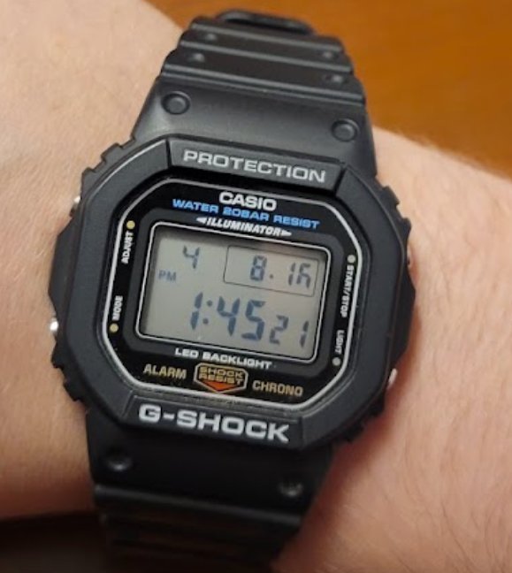
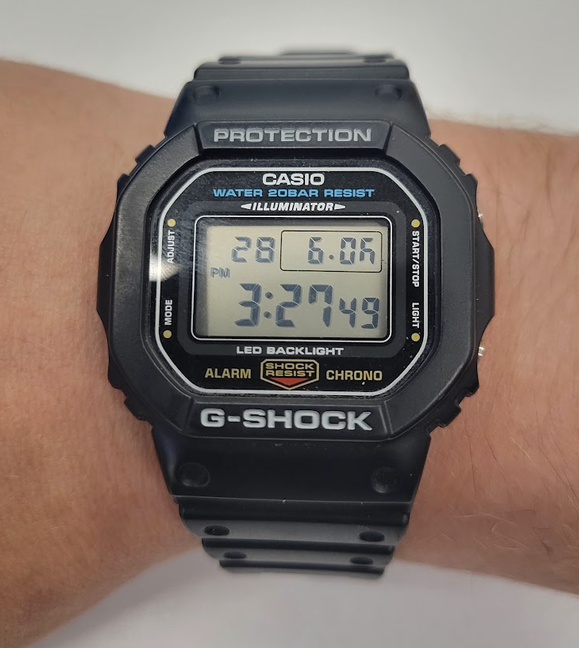
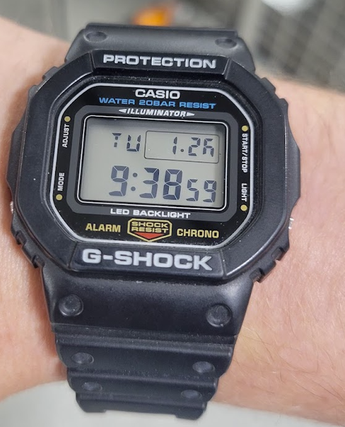
4.0 volts
How to change the LCD Voltage
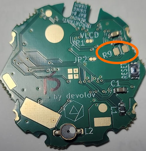
For those of you who want to change the LCD voltage for a better contrast, you just need to solder an 0805 resistor on the R9 pad. Use the table below to find what resistor to use for each voltage. I have only went up to 4.0V for my daily wearer, and going to any voltage above 3.6V is a risk to the watch.
| Voltage | Resistor for R9 | Suggested part |
|---|---|---|
| 3.6 V | Don't populate | - |
| 3.8 V | 68K | RMCF0805FT68K0 |
| 4.0 V | 41.2K | ERA-6AEB4122V |
| 4.3 V | 28.7K | RM10F2872CT |
| 4.5 V | 16K | RM10F1602CT |